
How Ag/AgCl Electrodes Work in Ussing Chamber Experiments

Ag/AgCl electrodes sit at the heart of every Ussing chamber experiment. They convert tiny ionic currents and voltage differences in your epithelial preparation into stable electrical signals your clamp can measure. When they are designed, filled, and maintained correctly, you get clean Isc, TEER, and voltage data. When they are not, you get drift, noise, and artifacts that look like “biology” but are really hardware.
Why Ag/AgCl Electrodes Are Used in Ussing Chambers
Most epithelial transport studies need a stable reference potential and low-noise current path between the apical and basolateral sides of the tissue. Silver/silver chloride (Ag/AgCl) electrodes provide:
- A well-defined electrochemical potential based on the Ag/AgCl/Cl⁻ redox couple.
- Low polarization when small currents pass during voltage clamp.
- Good stability over time when chloride activity is controlled.
- Compatibility with physiological saline solutions used in Ussing chambers.

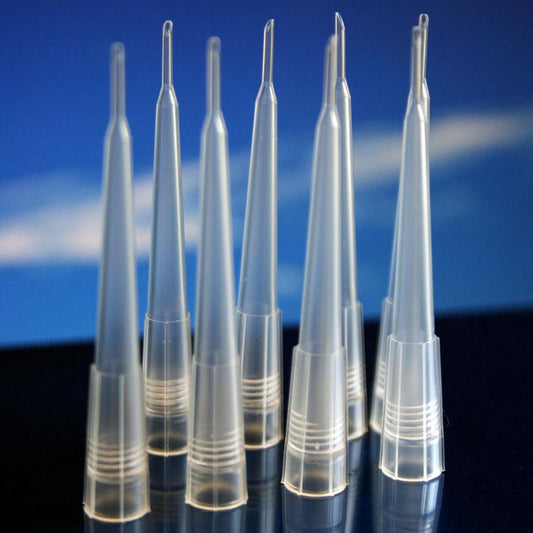
Inside an Ag/AgCl Electrode: Basic Anatomy
A typical Ussing chamber electrode assembly is more than just a wire dipped into saline. It is a system of components designed to isolate the tissue from metal surfaces and maintain stable chloride activity.
| Component | Role in the system |
|---|---|
| Ag/AgCl wire or pellet | Electroactive surface where Ag ⇌ AgCl + e⁻ couples to Cl⁻ in the filling solution. |
| Internal filling solution (e.g., 3 M KCl) | Provides fixed chloride concentration to stabilize electrode potential. |
| Agar–salt bridge | Separates metal and high-chloride filling solution from the tissue bath while allowing ion conduction. |
| Tip opening near the chamber | Where the bridge contacts the bath solution and completes the circuit through the tissue. |
Voltage vs Current Electrodes in Ussing Chambers
Most Ussing systems use separate electrode pairs for voltage sensing and current passing. This helps minimize artifacts during clamp steps and improves TEER and Isc accuracy.
Voltage-sensing (potential) electrodes
- Placed close to the tissue on each side to measure the transepithelial voltage (Vt).
- Draw almost no current, reducing polarization of the Ag/AgCl surface.
- Feed into the high-impedance input of the clamp amplifier.
Current-passing electrodes
- Placed farther from the tissue, often in side reservoirs.
- Carry the current imposed by the voltage clamp to maintain Vt at the commanded value.
- Are more susceptible to polarization if the system is poorly designed or solutions are wrong.

How Salt Bridges Protect Your Tissue and Your Signal
Salt bridges play a central role in maintaining both tissue integrity and signal quality in Ussing chamber experiments. The agar salt bridge forms the controlled electrical connection between the Ag/AgCl electrode system and the chamber bath while physically separating the electrode materials from the biological preparation.
By isolating the metal electrode surface and concentrated internal filling solution from the tissue bath, the salt bridge prevents chemical contamination that could damage epithelial cells or alter transport properties. At the same time, it allows ionic current to pass freely, completing the electrical circuit required for voltage and current measurements.
Salt bridges also help stabilize measured voltages by reducing liquid junction potentials. They achieve this by using a solution with high ionic strength and a stable chloride concentration, which minimizes potential differences that can arise when solutions of differing composition meet. This stability is especially important during long experiments or protocols that involve solution exchanges on one or both sides of the tissue.
The physical structure of the agar matrix further improves performance by limiting convection and slowing diffusion. This helps maintain a consistent ionic environment at the electrode interface over time, reducing slow baseline drift and high frequency noise in recorded signals.
In practice, salt bridges are typically prepared using concentrated potassium chloride or a similar chloride salt suspended in agar. The bridge solution must be chemically compatible with both the internal electrode filling solution and the chamber perfusate. Cracks, discoloration, or trapped air bubbles in the bridge disrupt ionic continuity and are common sources of noise and instability. For this reason, regular inspection and replacement of salt bridges are essential for obtaining reliable, publication quality Ussing chamber data.
Common Problems with Ag/AgCl Electrodes
When electrodes are not maintained, they become a hidden source of drift and noise. Below are frequent failure modes and what they look like in the data.
| Problem | What you see | Likely cause |
|---|---|---|
| Slow baseline drift | Vt or Isc gradually shifts over minutes | Aged AgCl layer, chloride depletion, or junction potentials changing as solutions mix. |
| Increased noise | High-frequency fluctuations on otherwise stable traces | Poor grounding, loose connections, cracked bridges, or air bubbles near the tip. |
| Step artifacts | Distorted clamp steps that do not settle cleanly | Current electrode polarization or incorrect electrode placement. |
| Offset mismatch | Large apparent Vt with no tissue mounted | Voltage electrodes not balanced; asymmetrical filling solutions or junction potentials. |
Maintenance Tips for Reliable Ag/AgCl Electrodes
Routine maintenance keeps the electrode potential stable and protects your investment in Ussing hardware.
- Inspect and refill electrode bodies on a regular schedule; top up or replace filling solution if levels fall.
- Replace or re-chloridize Ag wires when the AgCl layer appears dark, patchy, or damaged.
- Remake agar bridges if they are cracked, discolored, or have air bubbles along their length.
- Store electrodes properly, typically in compatible chloride solution rather than dry.
- Check offset with the chamber filled but no tissue present, and zero the system before each experiment.
How Electrode Design Affects Ussing Chamber Data Quality
Electrode design choices directly influence how much of your “signal” is biology and how much is hardware. Factors include:
- Bridge geometry: Short, wide bridges lower resistance and reduce noise.
- Distance to tissue: Voltage electrodes positioned near the tissue reduce series resistance and improve TEER accuracy.
- Solution choice: Matching ionic composition across bath and bridge minimizes junction potentials.
High-quality Ag/AgCl electrode systems and well-designed Ussing chambers work together to deliver stable transepithelial voltage, TEER, and Isc recordings that truly reflect epithelial transport.
Liquid Junction Potentials and the Importance of High Chloride Concentration
Liquid junction potentials arise whenever two solutions with different ionic composition or concentration come into contact, such as at the interface between an electrode filling solution and the tissue bath. Because different ions move at different speeds, a small voltage develops at this boundary. This voltage is not related to the tissue and instead reflects unequal ion mobilities across the junction.
Using a high chloride concentration in Ag/AgCl electrodes and salt bridges minimizes these potentials for two reasons. First, chloride ions have relatively high and predictable mobility, so the voltage generated at the junction is small and stable. Second, when both sides of the junction are dominated by the same ion (Cl⁻), differences in ion diffusion are reduced, keeping the junction potential close to constant over time.
In Ussing chamber systems, concentrated KCl in the electrode and bridge ensures that any liquid junction potential is small, stable, and reproducible. This prevents slow voltage offsets or drift that could otherwise be mistaken for changes in transepithelial voltage or transport activity, improving the reliability of electrophysiological measurements.
Checklist: Is Your Electrode System Ready for Publication-Quality Data?
- Voltage and current electrodes clearly identified and correctly placed.
- Filling solutions fresh and at the correct concentration.
- Agar bridges intact, bubble-free, and correctly oriented.
- Offsets checked and zeroed with no tissue mounted.
- Noise level verified before starting your experimental protocol.
With properly designed and maintained Ag/AgCl electrodes, your Ussing chamber becomes a precise instrument for quantifying epithelial transport, not a source of unexplained drift and noise.
Ag/AgCl Electrodes in Ussing Chambers
Why are Ag/AgCl electrodes preferred in Ussing chamber experiments?
Ag/AgCl electrodes are preferred in Ussing chamber experiments because they provide a stable, reproducible electrochemical interface between the biological preparation and the electronic measurement system. Their behavior is governed by the well-defined silver/silver chloride redox reaction, which establishes a predictable electrode potential as long as chloride activity is controlled.
Unlike bare metal electrodes, Ag/AgCl electrodes exhibit low polarization when small currents pass through them. This is critical in voltage-clamp and TEER measurements, where even minor polarization at the electrode surface can introduce voltage offsets or distort clamp responses. The reversible Ag ⇌ AgCl + e⁻ reaction allows charge to be transferred without large changes in electrode potential, preserving measurement fidelity.
Ag/AgCl electrodes are also chemically compatible with physiological saline solutions used in Ussing chambers. When paired with a high-chloride internal filling solution and an appropriate salt bridge, they maintain a stable reference potential over long experiments, minimizing baseline drift. This stability is essential for detecting small changes in transepithelial voltage or short-circuit current that reflect epithelial transport rather than electrode behavior.
Finally, Ag/AgCl electrodes integrate well into four-electrode Ussing chamber configurations, where separate voltage-sensing and current-passing pathways are required. Their predictable impedance and long-term stability make them suitable for both low-current voltage measurements and sustained current injection during clamp steps. Together, these properties make Ag/AgCl electrodes the standard choice for producing reliable, publication-quality Isc, TEER, and transepithelial voltage data.

What role does chloride concentration play in Ag/AgCl electrode stability?
Chloride concentration is the primary factor that determines the stability and reproducibility of an Ag/AgCl electrode’s electrical potential. The electrode operates through the reversible redox reaction:
AgCl (solid) + e⁻ ⇌ Ag (solid) + Cl⁻ (solution)
Because this equilibrium directly involves chloride ions, the electrode potential depends on chloride activity in the solution surrounding the Ag/AgCl surface. If chloride concentration changes, the electrode potential shifts accordingly, introducing voltage offsets or slow drift that are unrelated to the biological tissue.
In Ussing chamber systems, this is controlled by using a high, fixed chloride concentration in the electrode’s internal filling solution, commonly 3 M KCl. This high and stable chloride activity “locks” the Ag/AgCl equilibrium in place, making the electrode potential insensitive to small changes in temperature, current flow, or bath composition. As long as the filling solution remains concentrated and uncontaminated, the electrode potential remains stable over time.
The agar–salt bridge plays a complementary role by maintaining ionic continuity between the internal filling solution and the bath while limiting mixing. If chloride slowly diffuses out of the electrode or is diluted by bath solution, due to evaporation, leaks, or degraded bridges—the effective chloride concentration at the Ag/AgCl surface drops. This leads to gradual baseline drift, apparent voltage offsets, or increased noise during long recordings.
In practical terms, stable chloride concentration ensures that measured voltages reflect the electrical properties of the epithelium, not slow changes in electrode chemistry. Maintaining correct filling solution concentration, minimizing dilution at the bridge, and regularly servicing electrodes are therefore essential for reliable, publication-quality Ussing chamber data.
Why are salt bridges necessary between the electrode and the tissue bath?
Salt bridges are necessary because they provide an electrically conductive connection between the Ag/AgCl electrode and the tissue bath while preventing direct contact between the metal electrode system and the biological preparation. This separation is essential for both signal stability and tissue integrity in Ussing chamber experiments.
Ag/AgCl electrodes require a high, fixed chloride concentration to maintain a stable potential, typically supplied by a concentrated internal filling solution such as KCl. Direct exposure of this solution or the metal electrode surface to the tissue bath would alter bath composition, damage the tissue, and introduce uncontrolled electrochemical reactions. The salt bridge acts as a controlled ionic pathway that allows current to flow without allowing bulk mixing of solutions.
Salt bridges also reduce liquid junction potentials, which arise when solutions of different ionic composition meet. By using a high-conductivity, chloride-rich bridge solution that is compatible with both the electrode filling solution and the bath, the magnitude and variability of these junction potentials are minimized. This helps ensure that measured voltages reflect transepithelial properties rather than chemical gradients at solution interfaces.
In addition, the physical structure of the agar-based bridge dampens convection and limits rapid diffusion, maintaining a stable ionic environment over long experiments. Cracks, air bubbles, or degradation in the bridge disrupt this continuity, leading to increased noise, drift, and unstable clamp behavior.
In summary, salt bridges protect the tissue from electrode materials, stabilize the electrochemical environment of the electrode, and preserve the integrity of voltage and current measurements. Without properly designed and maintained salt bridges, Ag/AgCl electrodes cannot deliver reliable or interpretable Ussing chamber data.
What is the difference between voltage-sensing and current-passing electrodes?
Voltage-sensing and current-passing electrodes serve fundamentally different roles in an Ussing chamber system, and separating these functions is essential for accurate electrophysiological measurements.
Voltage-sensing (potential) electrodes are used to measure the transepithelial voltage (Vt) across the tissue. They are placed as close to the epithelial surface as possible on both the apical and basolateral sides and are connected to the high-impedance inputs of the voltage clamp amplifier. Because these electrodes draw essentially no current, they experience minimal polarization, allowing the measured voltage to reflect only the electrical properties of the tissue rather than changes at the electrode surface or in the bathing solution.
Current-passing electrodes, in contrast, are responsible for delivering the current required by the voltage clamp to hold the tissue at a commanded voltage. These electrodes are typically positioned farther from the tissue, often in side reservoirs, so that voltage drops associated with current flow do not distort the local voltage measurement near the epithelium. Since current-passing electrodes carry substantial current during clamp steps, they are more susceptible to polarization, junction potentials, and resistance changes if electrode condition, bridge geometry, or solution composition is not well controlled.
Separating voltage sensing from current delivery minimizes measurement artifacts, improves the stability of clamp steps, and enhances the accuracy of Isc and TEER calculations. In well-designed Ussing chamber systems, this four-electrode arrangement ensures that the voltage recorded represents the tissue alone, while the current required to maintain that voltage is delivered without contaminating the measurement.
How does poor electrode placement affect TEER and Isc measurements?
Incorrect placement increases series resistance and polarization effects, leading to noisy signals, unstable baselines, and distorted clamp steps that can be mistaken for biological responses.
What causes slow baseline drift in Ussing chamber recordings?
Slow baseline drift in Ussing chamber recordings is most often caused by gradual changes in the electrode system rather than true biological activity. These changes alter the reference potential or series resistance over time, producing apparent shifts in transepithelial voltage (Vt) or short-circuit current (Isc).
One common cause is instability of the Ag/AgCl electrode surface. As the AgCl layer ages, becomes damaged, or is partially reduced, the electrode potential can slowly change. This effect is amplified if chloride concentration near the electrode decreases due to evaporation, dilution, or depletion of the internal filling solution.
Salt bridge degradation is another frequent contributor. Slow diffusion of chloride from the bridge into the bath, partial mixing of solutions, or the presence of microcracks or air bubbles can change junction potentials over time. These gradual chemical changes appear in the data as smooth voltage or current drift rather than abrupt noise.
Baseline drift can also result from temperature changes, since electrode potentials and solution conductivities are temperature dependent. Even small, uncorrected temperature gradients across the chamber can produce slow shifts in measured signals during long experiments.
Less commonly, drift may arise from mechanical or electrical factors, such as creeping changes in electrode positioning, relaxation of connections, or slow changes in amplifier offsets if the system is not properly zeroed before tissue mounting.
Because these effects occur on timescales similar to biological responses, slow baseline drift can easily be misinterpreted as changes in epithelial transport. Verifying electrode condition, maintaining stable chloride concentration, ensuring intact salt bridges, and zeroing the system with no tissue present are essential steps for distinguishing true biology from hardware-induced drift.
Why do Ag/AgCl electrodes sometimes produce excessive noise?
Excessive noise in Ag/AgCl electrode recordings is usually caused by problems in the electrode system rather than by biological activity in the tissue. Noise arises when the electrical pathway between the electrode and the amplifier becomes unstable, resistive, or intermittently interrupted.
One common source of noise is poor electrical continuity. Loose connectors, oxidized contacts, or partially broken wires introduce fluctuating resistance that appears as high frequency noise in voltage or current traces. Even small mechanical disturbances can worsen this effect during an experiment.
Salt bridge defects are another frequent cause. Air bubbles trapped near the bridge tip, cracks in the agar matrix, or partial drying disrupt ionic conduction. These discontinuities cause rapid changes in local resistance, which are detected as noise by the amplifier. Because the voltage sensing electrodes draw very little current, even minor interruptions can have a large effect on signal quality.
Noise can also result from inadequate grounding or shielding. Poor grounding allows environmental electrical interference from nearby equipment, lighting, or power lines to couple into the recording system. This interference often appears as rhythmic or broadband noise that persists even when the tissue signal is stable.
Electrode surface condition plays an additional role. Damaged, uneven, or partially reduced silver chloride layers can produce unstable electrode potentials. These microscopic instabilities translate into fluctuating voltages when measured at high gain, especially during voltage clamp operation.
Finally, solution related issues contribute to noise. Inconsistent chloride concentration, contamination of the filling solution, or slow mixing between bridge and bath solutions can create local potential fluctuations. Temperature instability can further amplify these effects by altering solution conductivity and electrode behavior.
In practical terms, excessive noise usually indicates a hardware issue that should be addressed before interpreting any biological signal. Inspecting connections, replacing compromised salt bridges, refreshing filling solutions, confirming proper grounding, and verifying electrode condition with no tissue present are essential steps for restoring stable, low noise Ussing chamber recordings.
How often should Ag/AgCl electrodes be maintained or reconditioned?
Ag/AgCl electrodes should be maintained on a regular, preventive schedule, not only when problems appear in the data. The exact frequency depends on usage intensity, experiment duration, and solution conditions, but some general guidelines apply.
For routine use, electrodes should be visually inspected before each experiment. This includes checking filling solution levels, confirming that the solution is clear and uncontaminated, and verifying that salt bridges are intact and free of air bubbles. Small issues at this stage often prevent drift or noise later in the experiment.
Replenishing or replacing the internal filling solution should be done whenever solution levels drop, evaporation is visible, or experiments involve long recording periods. Even partial dilution of the filling solution can affect chloride concentration and electrode stability, so topping off is not always sufficient. Periodic full replacement is recommended.
Re-chloridizing the silver element is typically required after repeated use, extended current passing, or whenever the AgCl layer appears dark, uneven, patchy, or mechanically damaged. In active laboratories, this may be necessary every few weeks. In lower use settings, it may be needed less frequently, but visual inspection should guide the decision rather than a fixed calendar interval.
Salt bridges require the most frequent attention. They should be replaced immediately if cracks, discoloration, dehydration, or trapped air bubbles are observed. Even intact bridges are often remade on a regular cycle to ensure consistent performance, especially for experiments intended for publication quality data.
As a best practice, electrode performance should be verified with the chamber filled and no tissue mounted after any maintenance step. Stable baselines, low noise, and reasonable offsets confirm that the electrode system is ready for use. Regular maintenance reduces variability, prevents data artifacts, and extends the usable life of Ag/AgCl electrodes in Ussing chamber experiments.
Can electrode issues mimic biological effects in epithelial tissues?
Instability in Ag/AgCl electrode potential can cause slow shifts in measured transepithelial voltage or short circuit current that look like changes in transport activity. These shifts are often due to aging or damaged AgCl layers, changes in chloride concentration, or gradual mixing at the salt bridge rather than true alterations in epithelial physiology.
Electrode polarization is another frequent issue. When current passing electrodes are poorly conditioned or improperly positioned, polarization effects can distort clamp steps and recovery phases. These distortions may appear as altered channel activity, delayed responses, or abnormal resistance changes that could be mistaken for tissue behavior.
Noise introduced by cracked bridges, trapped air bubbles, loose connections, or inadequate grounding can create fluctuations that resemble unstable or oscillatory biological signals. In some cases, these artifacts occur intermittently, making them difficult to distinguish from real cellular events without careful controls.
Because electrode artifacts often develop on similar time scales as biological responses, they can be especially misleading. Verifying electrode performance with no tissue present, checking offsets, monitoring baseline stability, and confirming low noise levels are essential steps for ensuring that observed signals reflect epithelial transport rather than hardware induced effects.
How can you verify electrode performance before starting an experiment?
You verify electrode performance by confirming that the electrode system produces a stable, low-noise baseline and reasonable offsets under controlled conditions before any tissue is mounted.
-
Fill the chamber with your normal bath solutions (no tissue). Let temperature and perfusion stabilize so you’re not judging the system during warm-up transients.
-
Confirm correct electrode roles and placement. Voltage-sensing electrodes should be positioned close to where the tissue will sit; current-passing electrodes should be in their intended reservoirs/positions and securely connected.
-
Check for a stable baseline. With no clamping steps or stimulation, Vt and/or Isc traces should be steady (no slow drift) and quiet (no high-frequency jitter).
-
Measure and zero the offset (“open-circuit” or no-tissue offset). A large apparent Vt with no tissue present usually indicates mismatched filling solutions, junction potentials, or unbalanced voltage electrodes.
-
Run a simple clamp step test (if you use voltage clamp). Apply a small step and confirm the response settles cleanly without prolonged overshoot, oscillation, or strange stimulus artifacts, these often point to current electrode polarization, bad bridges, or bubbles.
-
Inspect bridges and electrode bodies immediately if anything looks off. Air bubbles near tips, cracked/discolored agar bridges, low filling solution levels, or loose connectors are common causes of drift and noise.
If the system is stable with no tissue, you’ve removed most hardware variables, so any changes after mounting are far more likely to be real tissue behavior.
Ag/AgCl electrodes
Ag/AgCl electrodes are not passive accessories in Ussing chamber experiments. They are fundamental components that determine whether measured voltages and currents reflect true epithelial transport or hidden hardware artifacts. Stable electrode potentials, well-designed salt bridges, and proper separation of voltage-sensing and current-passing pathways are essential for reliable Isc, TEER, and transepithelial voltage measurements.
Routine inspection, correct solution chemistry, and thoughtful electrode placement prevent drift, noise, and polarization effects that can otherwise obscure biological interpretation. When Ag/AgCl electrodes are designed and maintained correctly, the Ussing chamber functions as a precise electrophysiological instrument, producing data that are reproducible, interpretable, and suitable for publication-quality analysis.
Learn More
If you would like to learn more about Ag/AgCl electrode options, electrode configurations, or complete Ussing chamber systems optimized for stable electrophysiological measurements, you can request additional information or a quote from Physiologic Instruments. Our team can help identify electrode designs and system components that match your experimental requirements and measurement goals.